State of the art time-to-digital converter
 quTAG - state of the art time-to-digital converter
- Overview
- Specifications
- Jitter Measurement
- Extensions
- Applications
- Use cases
- Coding Examples
- Videos
- Downloads
Key Features
| Digital resolution 1 ps |
| Timing jitter down to 3.0 ps (RMS) / 7.0 ps (FWHM) |
| 100 MEvents/s max. rate |
| Up to 16 stop channels, 1 start channel |
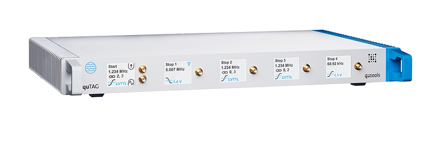
The quTAG is a high-end, easy-to-use time-to-digital converter and time tagging device designed for time correlated single photon counting (TCSPC). It is capable of detecting events with a digital resolution of 1 picosecond and a jitter under 10 ps RMS. Its user-adjustable design registers all signals between -3V up to +3 V, like the widely used LVTTL or NIM. It allows capturing up to 100 million time tags per second and uses a USB3.0 connection to transfer the extensive data. It is delivered with software for Windows and Linux with an easy-to-use graphical user interface. It can also be integrated in custom software. Examples for LabView, C/C++ and Python are included.
Standard model
This model features 1 start and 4 stop channels. A separate channel for external clock is available and easily accessible on the front panel. The device allows synchronizing with up to four standard models with all 16 stop channels using the same timebase and clock input. The software includes an analyzing tool for lifetime measurements and correlation functions (e.g. HBT measurements, fluorescence correlation spectroscopy).
Specifications
| Specification | Value | Unit |
|---|---|---|
| Digital resolution | 1 | ps |
| Timing jitter upgrade 2 channels | < 3.0 < 4.2 | ps RMS /√2 * ps RMS |
| Timing jitter | < 7.1 < 10 | ps RMS /√2 * ps RMS |
| Number of stop channels | standard: 4 (max. 16) (basic: 2 obsolete) | |
| Max event rate | 100 25 | M/s (per device) M/s (per channel) |
| Input signals | -3 ... +3 e.g. LVTTL, NIM | V |
| Input connectors | SMA | |
| Connection to PC | USB 3.0 USB 2.0 | |
| Software | GUI, DLL, LabView, Python, Command line Windows, Linux | |
| Dimensions | 44 x 30 x 5 | cm x cm x cm |
All specifications can be found in the datasheet.
* See the tab “Jitter Measurement” for measurement method.
Jitter Measurement
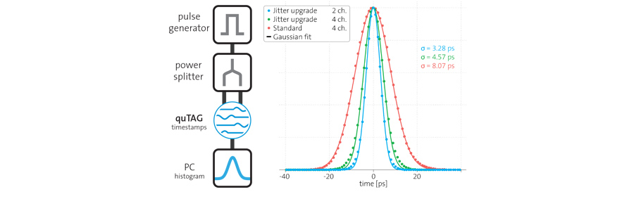
In order to measure the jitter, we generate an electrical pulse with steep edges. This pulse gets split into two by a power splitter and sent into two different inputs of the quTAG (i.e. start and stop-X or stop-X and stop-Y).
Then we use the quTAG software to generate a startstop-histogram. We fit a Gaussian function to this histogram and determine RMS and FWHM. The single channel jitter corresponds to σ / √2 from this two-channel measurement, assuming equal Gaussian contributions from both signals. The FWHM can be obtained by the standard deviation with the relation FWHM = 2 √2 ln 2 σ ≈ 2.35 σ.
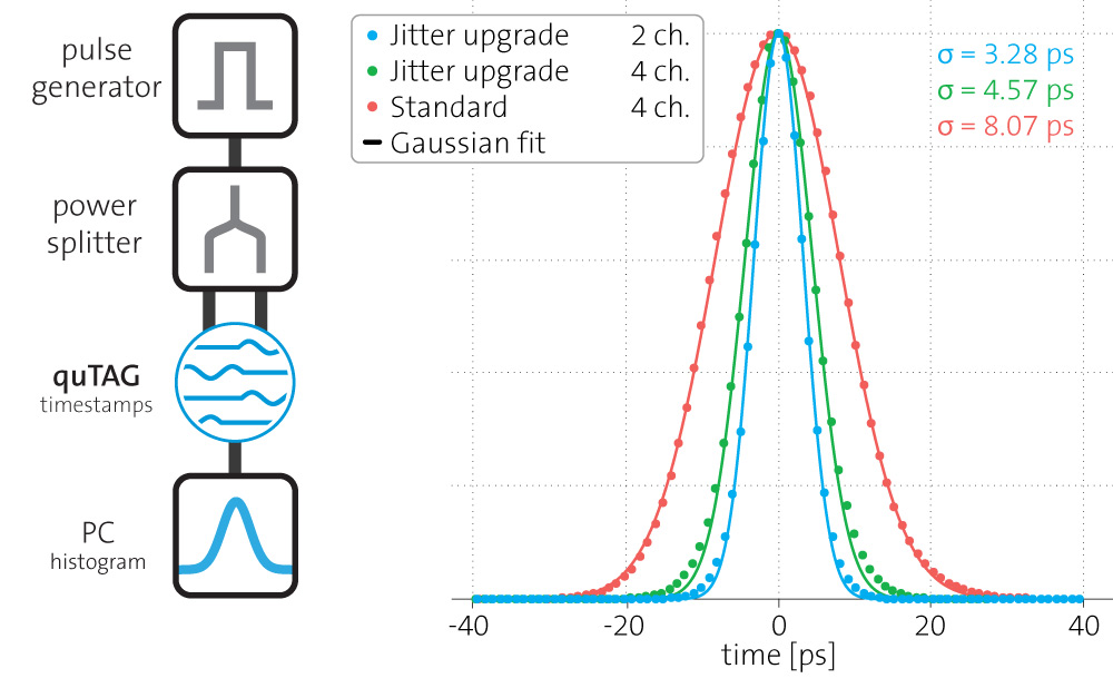
The evaluation of the measurements shown above yields the measured jitter and calculated single channel jitter for the different modes:
| Jitter upgrade 2 ch. ● | RMS [ps] | FWHM [ps] |
|---|---|---|
| Measurement | 3.28 | 7.71 |
| Single channel jitter | 2.32 | 5.49 |
| Jitter upgrade 4 ch. ● | RMS [ps] | FWHM [ps] |
|---|---|---|
| Measurement | 4.57 | 10.74 |
| Single channel jitter | 3.23 | 7.59 |
| Standard ● | RMS [ps] | FWHM [ps] |
|---|---|---|
| Measurement | 8.07 | 18.96 |
| Single channel jitter | 5.70 | 13.40 |
Extensions
| Available Extensions | standard model | |
|---|---|---|
| + Jitter upgrade | ||
|
This feature allows lower jitter at < 6.4 ps RMS on all four input channels. For lowest jitter of < 4.2 ps RMS, two channels can be combined, leaving two stop-channels of one device for measurements. For optimal jitter results, recalibration with external signals might be necessary.
The single channel jitter corresponds to σ / √2 from this two-channel measurement, assuming equal Gaussian contributions from both signals.Leading to single channel jitter < 3.0 ps RMS/√2 (2 channels) and < 4.5 ps RMS/√2 (4 channels). |
||
| + Stop channel extension | ||
|
The quTAG basic features two stop channels that can be extended by up to two more flexible stop channels. The quTAG standard has all 4 stop channels enabled by default.
|
||
| + Lifetime software | ||
|
This software addon enables the user to analyze lifetime measurements on the fly. It calculates the histograms, fits exponential decreases and takes response function of the system into account.
|
||
| + Correlation software | ||
|
This software extension is intended for calculating the correlation function, as needed for example in Hanbury Brown-Twiss experiments or fluorescence correlation spectroscopy. Standard functions can be fitted to assess the relevant parameters.
|
||
| + Clock Input | ||
|
The quTAG can be synchronized to an external clock of 10 MHz to allow more precise long-term accuracy.
|
||
| + Synchronization between devices | ||
|
This extension allows you to synchronize up to 4 quTAG devices. By this, up to 16 equal stop channels are offered and behave like one device – all sharing the same clock input and time base.
|
||
| + Marker Input | ||
|
This extension allows the use of additional input channels with less resolution that can be used for your trigger signals (e.g. pixel clock, line clock). These inputs are included in your timeline and help you sorting and assigning your timestamps.
|
||
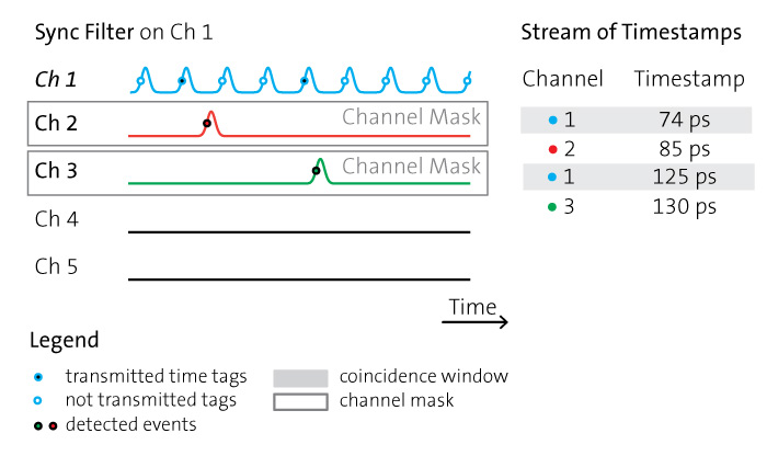
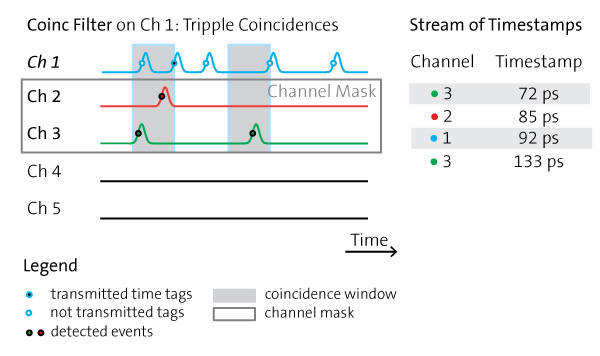
| + Filters / Virtual Channels | ||
|
This extension allows you to enable user-defined filters or virtual channels (e.g. coincidence and sync filters or artificial dead time). This filtering happens inside the device so that you save bandwith on your USB connection.
|
||
| + User-defined Clock frequency | ||
|
Allow to use any frequency between 1-100 MHz as clock input for long-term accuracy.
|
||
| + Start Channel as Input | ||
|
The start channel can be converted to another stop channel allowing the device to have 5 completely equal input channels with 1 ps resolution.
|
||
| + Divider for stop channels | ||
|
This option allows you to enable a divider on all stop channels. This allows higher (periodic) frequencies to be recorded.
|
||
Additional extensions are available upon request. Customized solutions, e.g. signal outputs, are possible. Contact us for details!
Publications
- Towards Quantum Telescopes: Demonstration of a Two-Photon Interferometer for Quantum-Assisted Astronomy
J. Crawford et al., arXiv preprint (2023) - Evaluating a Stand-Alone Quantum-Dot Single-Photon Source for Quantum Key Distribution at Telecom Wavelengths
T. Kupko et al., arXiv preprint (2021) - Noiseless photonic non-reciprocity via optically-induced magnetization
X. Hu et al., Nature (2021) - Time-of-arrival detection for time-resolved scanning transmission X-ray microscopy imaging
S. Finizio et al., Journal of Synchrotron Radiation (2020) - Adaptive single photon detection under fluctuating background noise
Z. Chen et al., OSA Publishing (2020) - Tools for the performance optimization of single-photon quantum key distribution
T. Kupko et al., Nature (2020) - Hong-Ou-Mandel interference between independent III-V on silicon waveguide integrated lasers
C. Agnesi, et al., OSA Publishing (2019) - Sub-ns timing accuracy for satellite quantum communications
C. Agnesi et al., OSA Publishing (2019) - Experimental demonstration of quantum advantage for one-waycommunication complexity
N. Kumar et al., arXiv preprint (2018) - A photonic quantum walk with a four-dimensional Coin
L. Lorz et al., arXiv preprint (2018) - Towards quantum communication from global navigation satellite system
L. Calderaro et al., IOP Publishing (2018)
General Applications
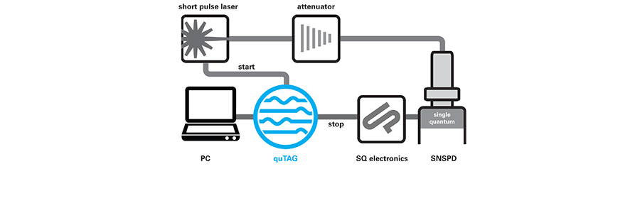
Laser trigger as Start, Single Quantum SNSPD as Stop
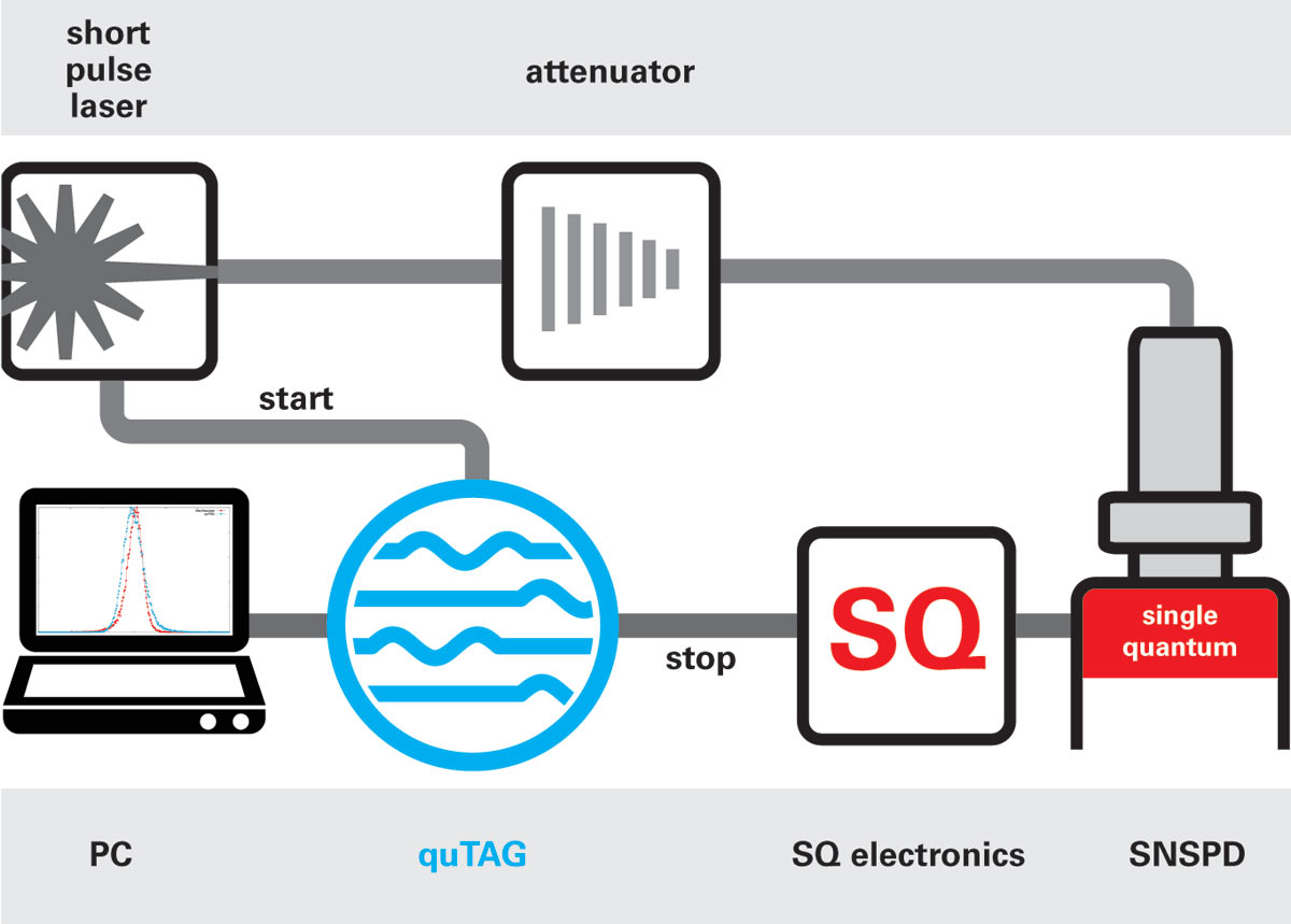
We measured a time difference histogram between the trigger pulse from the laser as start and the SQ detector signal as stop.
This is basically the setup for a Fluorescence Lifetime Imaging (FLIM) measurement..
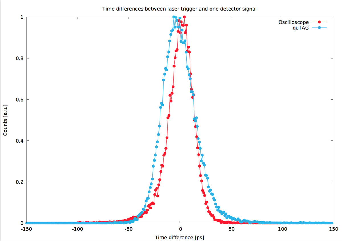
Results:
Whole system response function (blue, measured with quTAG): Timing jitter 17.8 ps RMS, 35.9 ps FWHM
For comparison: Detector response function (red, measured with fast oscilloscope): Timing jitter 14.5 ps RMS, 26.1 ps FWHM.
One SQ Detector as Start, another one as Stop

Here, we measured the time difference histogram between one of the two SQ SNSPDs as Start and the other one as Stop pulse.
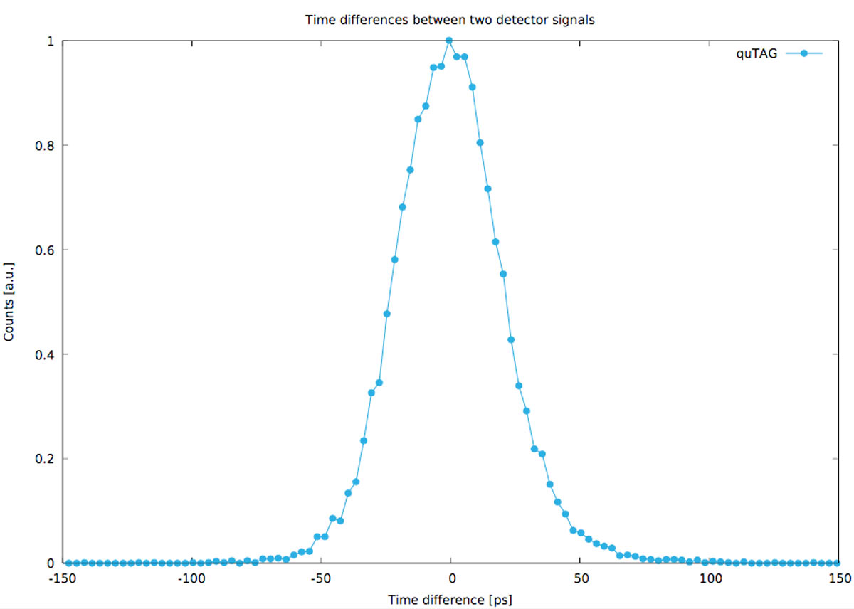
Results:
Timing jitter of 2 SQ SNSPDs measured with the quTAG (blue): 21.6 ps RMS, 45.6 ps FWHM.
Overview of quick and easy Python Coding Examples
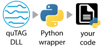
Python is a popular coding language for labs and institutes. Therefore, qutools created a Python file to wrap all the DLL or SO (Win/Linux) functions to gain quick and easy control of the hardware.
The following list shows the different examples using this wrapper. An explanation is added to each code.
- Retrieve Countrates and Coincidences
- Live Plotting of Countrates with matplotlib
- Create and retrieve a histogram of two channels
- Live Plotting of the histogram with a changing channel delay
- Retrieve timestamps
- Write timestamps to a file on the PC
- Change different settings of the quTAG
| Download all Python Examples | 07/2022 | 0.7 MB | zip |
| quTAG software manual V1.5.0 – Example explanation | 10/2019 | 0.3 MB |
First Coding Example: How to retrieve Countrates
The following codes show how to quickly connect to the quTAG via Python. The quTAG.py file wraps all DLL functions to get simple access via your own code.
In the first example qutag-GetCoincCounter-starter_example.py we are retrieving countrates and coincidences of the quTAG and its input channels.
# quTAG Python example codes based on the quTAG Python wrapper.
# Run with Python 3.7.3 (32bit), numpy-1.13.3 and Windows 7 (64bit)

# Import the python wrapper which wraps the DLL functions.
# The wrapper should be in the same directory like this code in the folder '../QUTAG-V1.5.0/userlib/src'.
try:
	import QuTAG
except:
	print('Time Tagger wrapper QuTAG.py is not in the search path.')


#Initialize the quTAG device
qutag = QuTAG.QuTAG()
# Set the exposure time (or integration time) of the internal coincidence counters in milliseconds, range = 0...65535
qutag.setExposureTime(1000) # 1000 ms exposure time
# Give some time to accumulate data
time.sleep(1) # 1 second sleep time with 100ms exposure time would give ~10 times data we don't get

# Now let's retrieve the most recent values of the built-in coincidence counters from quTAG.
# The array contains count rates for all 5 channels and rates for coincidences of events detected on different channels. Events are coincident if they happen within the coincidence window (qutag.setCoincidenceWindow).
# The coincidence counters are not accumulated, i.e. the counter values for the last exposure (see setExposureTime ) are returned.
data,updates = qutag.getCoincCounters()
print('Updates since last call: ', updates, '| latest Data: ', data)
# updates	Output: Number of data updates by the device since the last call. Pointer may be NULL.
# data	        Output: Counter Values. The array must have at least 31 elements.
#                       The Counters come in the following channel order with single counts and coincidences:
#                       0(5), 1, 2, 3, 4, 1/2, 1/3, 2/3, 1/4, 2/4, 3/4, 1/5, 2/5, 3/5, 4/5, 1/2/3, 1/2/4, 1/3/4, 2/3/4, 1/2/5, 1/3/5, 2/3/5, 1/4/5, 2/4/5, 3/4/5, 1/2/3/4, 1/2/3/5, 1/2/4/5, 1/3/4/5, 2/3/4/5, 1/2/3/4/5
### see 'tdcbase.h' file reference for more info: function TDC_getCoincCounters(Int32 *data, Int32 *updates)
Videos
Datasheet & Manuals
| quTAG datasheet | 07/2022 | 0.3 MB | |
| quTAG manual V1.4.0 | 05/2019 | 0.9 MB | |
| quTAG software manual V1.5.0 | 10/2019 | 0.3 MB | |
| quTAG & Matlab technical note | 10/2019 | 0.3 MB | |
| quTAG brochure | 02/2022 | 2.4 MB |
Software
* Note! This software is compatible only with serial number T 01 0012 and newer! Please contact us if you own an older device!
| FTDI driver V1.2 | 10.4 MB | exe | |
| Python examples | 07/2022 | 0.7 MB | zip |
| DLL Documentation | 07/2022 | web |
|
Software for Serial Number
|
|||
| quTAG software installer V1.5.13 – 32 bit | 08/2025 | 33.4 MB | exe |
| quTAG Daisy & DLL V1.5.13 – 32 bit | 08/2025 | 34.0 MB | zip |
| quTAG Daisy & DLL V1.5.13 – 64 bit | 08/2025 | 21.4 MB | zip |
| quTAG software linux V1.5.13 – 64 bit | 08/2025 | 6.2 MB | tgz |
| Please contact info@qutools.com for SN: T 01 | |||
* Note! This software is compatible only with serial number T 01 0012 and newer! Please contact us if you own an older device!